Digital Inputs Inputs
OVERVIEW
Digital inputs may be configured in a number of ways to achieve the desired
functionality. Each Digital Input is processed as follows:
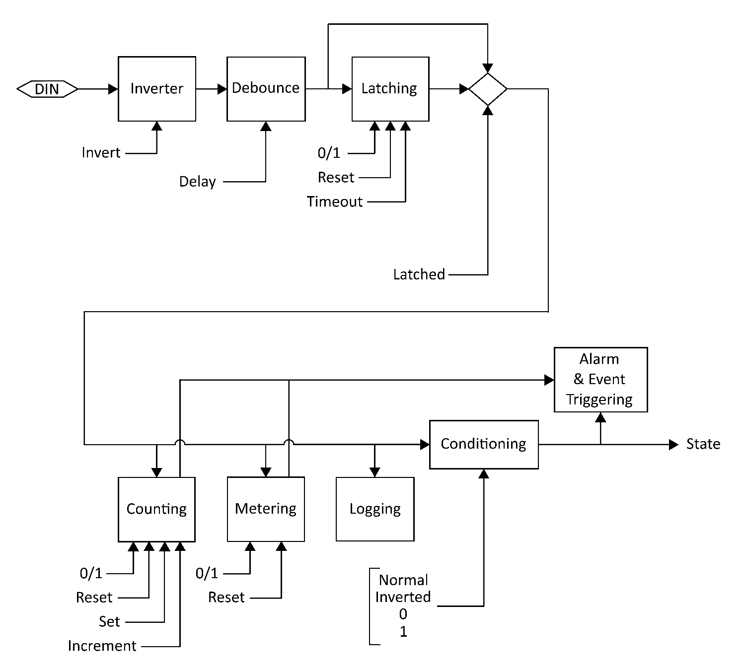
1. Sampled (Hardware)
2.
Inversion
3.
Debounce
4.
Latching
5.
Counting
6.
Metering
7.
Logging
8.
Conditioning
9.
Alarming
10. State Reported
All of the above steps are configurable through the WebUI and follow the
resulting Registry key settings.
REGISTRY NAMING
Each Digital Input has its own Registry section (node) which is numerically
defined. Presently there can be 4, 8 or 12 inputs depending on the JNIOR
model. Here we use [DIN] as a placeholder for the appropriate section name.
For example using 'din3' for Digital Input 3 we can set a text description
as follows:
reg IO/Inputs/din3/Desc = "Power Enabled"
NOTES
Registry keys are not case-sensitive however case is preserved when a key
is first defined. This improves readability without causing difficulty
in referencing keys.
SEE ALSO
HELP Topics:
IO/Inputs/[DIN]/Desc,
REG,
MODELS,
INPUTS
[/flash/manpages/registry.hlp:2523]